
Pre-Layout Simulation
Topology extracted from pcb placement: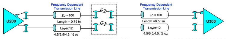
3D Models of Transitions generated and optimized: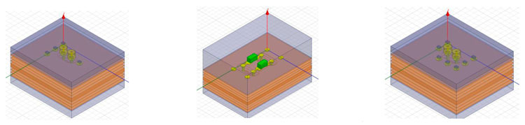
Insertion and Return Loss Results: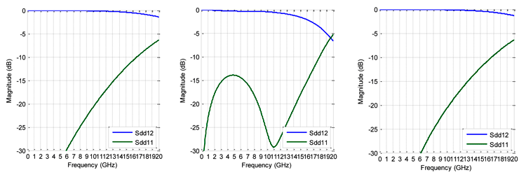

3D Model Example: Transition Vias on 1.0mm pitch: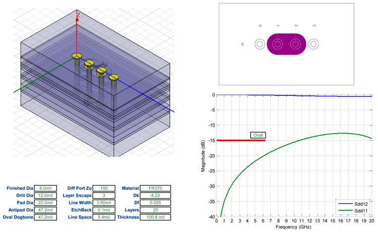
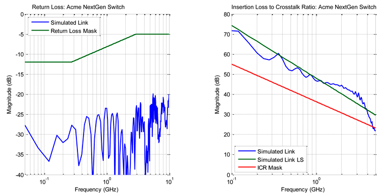
Channel Model results plotted against IEEE 802.3ap: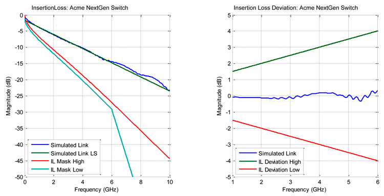
Summary of Pre-Layout Simulation
- 10.0 Gbps differential insertion loss, insertion loss deviation, return loss and insertion loss to crosstalk ratio masks are all met with margin.
- AC
cap transitions connecting to Layer 12 are right on the margin of
performance (-15dB at 5GHz), however the overall link performance shows
good results.
Changes required as a result of optimization:
- BGA Vias must alternate top and bottom layers for Tx and Rx.
- BGA Via top layer connections must be backdrilled to a 20mil stub.
- AC Cap must have a clearance on Layer 2 below the caps
- AC Cap antipad must be 40mil oval shape.
- See AC Cap dimensions on 3D model simulation sheet.